3. LASER CUTTING (PT. 1)
We wanted to build a fuel tank model that was easy enough to assembly, but at the same time, rigid enough to hold itself together when being transported.
Before moving onto laser cutting the fuel tank templates, Martin and Daniel briefly mentioned how it would be a good idea to do some test cuts first before proceeding.
EXPERIMENTATION

Before moving onto laser cutting the fuel tank templates, Martin and Daniel briefly mentioned how it would be a good idea to do some test cuts first before proceeding.
EXPERIMENTATION

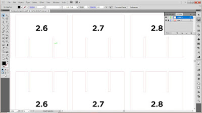
We made a couple of 'TEST models' on Adobe Illustrator, with each template joints ranging from 2.5 to 3mm. We wanted to determine the best joint width to go along with when assembling final skeleton model.
 |
| Laser Cutting the TEST model templates using Poplar plywood. |
Assembly and Testing
 |
| By assembling the parts together and wriggling the sides left and right, we were able to determine the rigidity and ease of each of the assemblies. |
Key insights: Initially on the Slicer program, we had set our joint thickness to 3mm.
However, after undergoing this experiment, we learnt that the 3mm thickness was the worst choice to proceed with due to how extremely wriggly assembly was and how easily the assembly fell apart when lifting it up on one side.
 |
| The 2.5mm joint thickness TEST model was too hard to assemble (tight joints). |
So we tried the same experimenting process with the rest of the assembled models, descending from 1mm at a time.
We all agreed that the 2.6mm thickness was the best option to go with, as the assembly process was manageable and the model was still rigid enough when being fiddled with.
Process Video of Joint Testing
CONTINUE ON TO PART 4...

Comments
Post a Comment